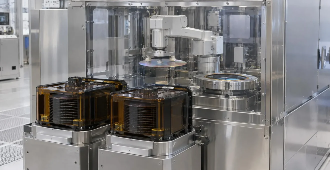
In semiconductor manufacturing, a wafer must reach the processing equipment in a controlled position and orientation, not simply arrive at the machine. An Equipment Front-End Module (EFEM) makes this possible by coordinating carrier access, robotic movement and wafer alignment within a controlled handling environment.
These functions are complementary but distinct. The load port provides access to the wafer carrier, the handling robot moves individual wafers, and the pre-aligner establishes their position and rotational reference. Their coordinated operation creates a reliable transfer path between factory material handling and the process tool.
Understanding the EFEM’s Three-Part Handling Architecture
An EFEM sits between the factory’s automated material handling system and a semiconductor process tool. It provides the mechanical and operational environment in which wafers move from a carrier to the equipment that performs a manufacturing operation.
The following comparison identifies each handling component by its responsibility and the operational result it provides. These distinctions help explain how the assemblies contribute to the same transfer path, even when their mechanical arrangement varies between equipment designs.
| Component | Primary responsibility | Operational output |
|---|---|---|
| Load port | Receives and docks the wafer carrier | Accessible carrier and transfer interface |
| Wafer-handling robot | Picks up and moves individual wafers | Physical transfer between stations |
| Pre-aligner | Determines wafer centre and rotational orientation | Positioned wafer ready for the next handling operation |
This functional architecture is consistent with the approach described in SEMI’s EFEM functional model, which describes the relationship between factory material handling and process equipment. Its value is architectural: it helps explain how the equipment’s functional elements fit together rather than prescribing one identical mechanical layout for every machine.
The practical consequence is that a problem in one component can interrupt the overall transfer operation even when the other assemblies remain operational. Understanding the individual responsibilities is therefore useful both for equipment integration and for maintenance.
When a fault affects a handling robot, pre-aligner or load-port interface, the condition of each assembly matters to the wider transfer chain. Eumetrys Robotics identifies repair, refurbishment and exchange services for these semiconductor equipment categories, with service information available by following this link.
How the Load Port Makes Wafer Carriers Accessible
The load port is the physical interface through which a wafer carrier enters the equipment. In a common 300 mm semiconductor configuration, that carrier is a Front Opening Unified Pod, or FOUP, designed to protect and transport wafers between manufacturing stations.
When the carrier arrives, the load port locates and docks it in the required position. The equipment then performs the appropriate access operations. Depending on the configuration, a door-opening mechanism exposes the carrier contents to the EFEM’s controlled handling area. The robot can subsequently access individual wafer slots.
Carrier-level identification and wafer-level alignment are separate operations. Carrier-management communication, including the functions addressed by SEMI E87, can coordinate carrier transfers, carrier association and verification of identification and slot-map information. These checks help the equipment establish which carrier is present and which wafer positions are available.
Carrier management is not wafer alignment. CarrierID and slot-map verification establish which carrier and wafer positions are available to the equipment. Centring and notch orientation are separate substrate-handling functions.
Once the carrier is accessible and the relevant equipment states permit handling, the robot can retrieve a wafer. The load port does not perform this individual wafer movement itself; it provides the access point that makes the transfer possible.
How the Wafer-Handling Robot Moves Individual Wafers
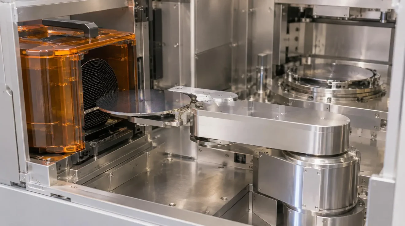
The wafer-handling robot is responsible for moving individual substrates between the load port, internal stations and the process-tool interface. Unlike the load port, which handles the carrier interface, the robot performs the physical pickup, movement and placement of each wafer.
Its end-effector is designed to support a wafer during transfer while limiting unwanted contact with its surface. Depending on the equipment, the robot may use a blade, fork or another specialised handling arrangement. Arm geometry and movement capabilities also vary. Some configurations use a single arm, while others use multiple arms to support different handling sequences.
During a transfer, the robot approaches the appropriate pickup location, positions its end-effector beneath or at the designated wafer support interface, and retrieves the substrate. It then moves the wafer to the receiving station and releases it at the specified position. The movement must account for mechanical clearances, wafer support and the readiness of the destination.
Robotic handling and wafer orientation are related but not necessarily performed by separate machines. An IEEE conference study, High-Precision Robotic Arm for Silicon Wafer Handling and Alignment in Small-Scale Semiconductor Fabrication, describes a custom dual-arm SCARA-based system that combines wafer movement with computer-vision notch detection and alignment. This small-scale research example demonstrates one possible integration approach, rather than a universal design for commercial EFEMs. The technical description is available in IEEE wafer-alignment research.
In systems using a separate pre-aligner, the robot transports the wafer to that station and retrieves it after positioning is complete. In other configurations, some alignment functions may be integrated into the robotic handling arrangement. The equipment design determines which architecture applies.
What the Pre-Aligner Corrects Before Processing
A wafer can be physically transferred to a process tool without necessarily having the required rotational orientation. The pre-aligner addresses this distinction by establishing a defined wafer position and orientation before the next operation.
In a typical separate-station arrangement, the robot places the wafer on a chuck or positioning stage. The system uses sensing technology to examine the wafer’s edge and determine its position. Depending on the wafer and equipment configuration, an edge notch or flat provides a reference for identifying rotational orientation.
The alignment process can involve two related corrections:
- Centring: determining and correcting the wafer’s position relative to the alignment stage or required handling reference.
- Rotational orientation: identifying the notch or another reference feature and establishing the required angular position.
Optical sensing and computer vision are possible approaches, although the exact technology depends on the equipment. A rotating stage can allow the system to observe the wafer edge and identify its reference feature. The resulting positional information allows the wafer to be presented in the required orientation for the next transfer.
These corrections matter because a wafer’s physical presence does not automatically mean that it is positioned correctly for the subsequent operation. The process tool may require a particular orientation or reference position, and the handling sequence must account for that requirement.
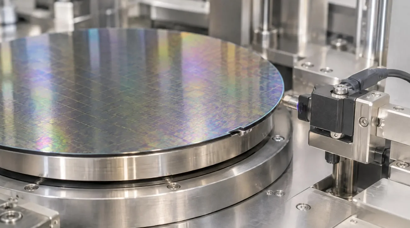
Not every wafer or process uses the same edge reference, and not every EFEM has an identical pre-alignment arrangement. The important distinction is functional: the alignment subsystem establishes the positioning information needed for the next operation, while the robot remains responsible for physical wafer movement.
How the Components Coordinate During a Wafer Transfer
The three subsystems work as part of a coordinated sequence. A transfer can proceed only when the relevant carrier, handling and receiving interfaces are ready. The controller manages the equipment states and movement permissions so that one operation does not conflict with another.
- The load port receives and docks the wafer carrier.
- The equipment confirms the relevant carrier and access states.
- The robot retrieves an individual wafer from the accessible carrier.
- The robot places the wafer on the pre-aligner when the configuration uses a separate alignment station.
- The pre-aligner establishes the required centre and rotational orientation.
- The robot retrieves the aligned wafer.
- The robot transfers it to the process-tool receiving interface.
Each movement depends on the outcome of the preceding operation and the readiness of the next interface. The carrier must be docked and accessible before the robot retrieves a wafer. Before placement, the robot and receiving station must be in compatible states, with the destination ready to accept the substrate. Where a separate pre-aligner is used, the robot cannot proceed with retrieval of the aligned wafer until the alignment operation has completed and the station permits pickup.
Delivery to the process tool likewise depends on the receiving interface being ready. The controller uses available equipment states and operation-completion confirmations to coordinate these transitions, while interlocks help prevent movements that conflict with mechanical or operational conditions. These are functional dependencies rather than a universal set of handshake signals: the exact confirmations, transfer paths and permissions vary with equipment design. Configurations with integrated robotic alignment can follow a different sequence without a separate pre-aligner transfer.
The same distinction provides a practical starting point when investigating handling problems. Rather than treating every interruption as a robot failure, maintenance personnel can consider which stage of the transfer sequence is affected.
- Carrier docking or access issue: examine the load-port interface and its reported state.
- Irregular wafer pickup or placement: examine robot motion, end-effector condition and calibration.
- Incorrect wafer orientation: examine pre-aligner sensing, stage movement and alignment settings.
- Intermittent transfer interruption: examine subsystem readiness, interlocks and controller records.
- Repeated failures: confirm findings against the equipment-specific maintenance documentation.
These checks are initial diagnostic directions, not definitive diagnoses. A carrier-access problem may involve the docking or access mechanism, while inconsistent placement can involve robot positioning or calibration. An orientation problem calls for examination of the alignment stage and its sensing system. Controller records and equipment-specific diagnostics help distinguish these possibilities before maintenance work is undertaken.